3D Printing
Galvin 2x3 with 4x5 holders
Introduction
Reducing backs - using a format smaller than the camera’s designed size - are relatively easy to design. The rear standard already has the space for the smaller format. Enlarging backs - using a format larger than the designed size - suffer from a lot of constraints. In simple terms, in order for a lens focused at infinity to be able to ‘see’ all the new format, the new format has to be mounted a fair way back from the rear standard. With shorter focal lengths and their wider angle of view, the rear extension has to be a lot, and the bellows extension small. With longer focal lengths and their narrower angle of view the bellows can play more of a part in the extension.
The original camera standard acts as a choke point, determining the relative positions of the lens and film based on the focal length. Unless the camera has an unusually large rear standard aperture, the range of focal lengths that can be used is much less than the original format, or a camera designed for the larger format.
The Galvin 2x3 has a 90mm square aperture in the rear standard, and a 125mm (5 inch) square panel for the back. A 4x5 film holder is 120mm wide, and 140mm from the base to the edge of the localing rib. The film aperture in the holder is 97mm x 120mm. So the Galvin 90mm x 90mm potential image area will fit inside the 4x5 film area. The film holder just fits the width of the Galvin back, and there is a little clearance between the Galvin rear frame and the standard without affecting the rear tilt.
This means a true enlarging back is not really viable - back tilt would be lost, and the focal lengths would be very restricted. However, an adapter to mount 4x5 film holders is possible.
Why Use 4x5 on the Galvin 2x3?
Film stock for the Galvin has to be either 120 roll film for 6x9/6x7/6x6/6x4.5 formats, or 2.25x3.25 inch sheet film. For sheet film this may mean cutting down 4x5 if anything other than the limited range manufactured in the native size is required. I have several cameras that can use 4x5, but only one that can use 2x3. So I am more likely to have loaded 4x5 holders on hand.
The down side is that 4x5 holders are larger and heavier (about 4 of 4x5 to 6 of 2x3 by weight), and a portion of the 4x5 film will be unused. Since a packaged sheet of 4x5 is about the same cost as a sheet of 2.25x3.25 for the same emulsion, this is not as big an issue as it might be.
The 9x9 format does offer one advantage over the 6x9, in that any proportion from the square is available.
How to do it
We need a Galvin lens board (it is the same size and fitting as the back), with an opening matching the 90x90mm opening in the rear standard. Onto this we need to graft the basics of a 4x5 film back - locating frame, ground glass and frame, spring retainers - while allowing clearances for the Galvin latches and not interfering with the tilt mechanism. The 4x5 mounting will have to be pushed back from the Galvin mounting a little for the clearances. This will change the rear tilt axis.
Because of the clearance needed for the tilt mechanism, the film holder will only be inserted from the top. This is not a big issue, as the effective format is square.
Moving the back away from the original Galvin back means that the back tilt is no longer on axis - so any tilt will also introduce a little rise (forward tilt) or fall (backward tilt) of the image relative to the initial position. How much of a problem this is will depend on the subject and any front adjustments.
Design
The basic Galvin 2x3 back is a variant on the lens board with a suitable aperture. Morton Kolve (amongst others) has designs for 4x5 backs, and parts can be adapted. The really new part is the tapered joining piece. If the spring mechanism uses shock cord cord, like the Kolve design, then the joining piece will need holes and cord tighteners.
We do not want to make the joining piece any deeper than necessary. The 4x5 holder will push the film plane back at least 5mm, and any change has to be accomodated by the bellows.
As is my usual practice, the design was done in OpenSCAD, drawing a little on the Galvin to Wista/Technika Adapter elements and measurements. The basic design starts with a Galvin board, and grafts on an asymmetric oblong funnel-like section that holds the necessary frame and cord stops for a shock cord sprung 4x5 back.
The most complex issue was keeping overhangs to a minimum to avoid needing supports. Some are still needed, and the unit really needs to be printed with a brim or raft for good corner adhesion. I chose to separate the panel that mounts on the rear standard, and print it separately. It needs to be the right thickness, and removing it from the main back print job reduces the support clean-up considerably.
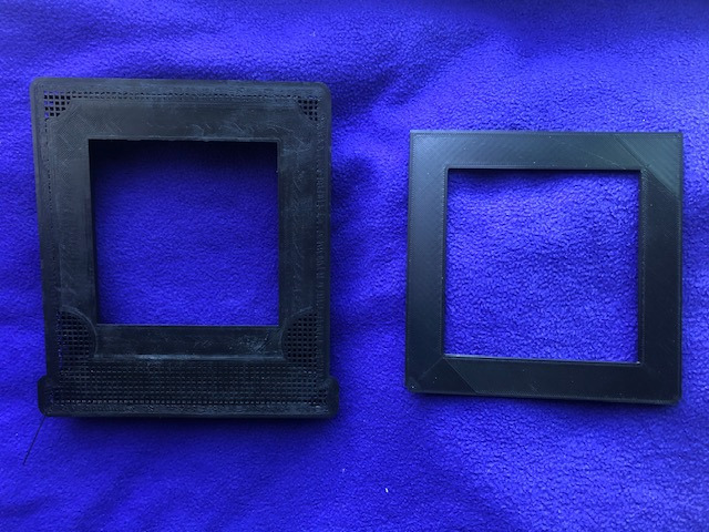
The two parts have to be glued together, with the clipped corners of the panel under the small corner cut-outs on the main back, and the aperture aligned.
Printing
This design has overhangs, which means some level of support is required. While the cut-aways above the Galvin rear standard retainers are conical, the only way to avoid supports is to make the back thicker. In practice, the supports can be cut away and gently sanded using a rotary tool and a sanding cylinder at low speed, before finishing with fine sandpaper. These areas are not visible, and a little black paint does a lot to hide any finishing marks.
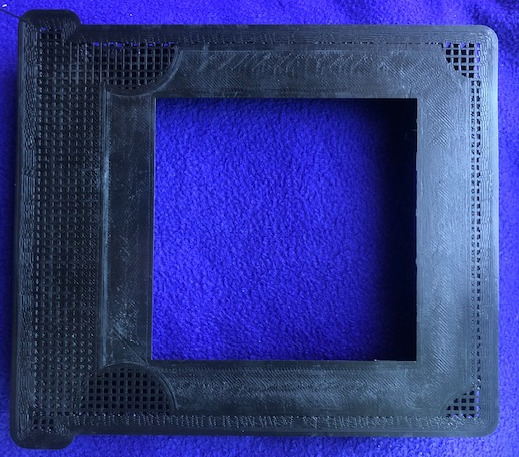
I found it best to print with a brim, but even so it does pay to make sure that the build plate adhesion is good - this is a big-ish area and the corners can lift. Print time at 66mm/s (33mm/s walls) for the main unit was around seven hours using a 0.4mm nozzle and 0.2mm layer height.
Assembling the Parts
Do a fit check with a 4x5 film holder (or Grafmatic) to make sure it fits the recess and the locating rib fits the channel. There is always a small chance of expansion or contraction. The channel has walls just over 1mm thick using a 0.4mm nozzle, so a little carving away is possible.
Make sure the Galvin plate is thick enough to clear the camera rear standard when fitted. If not, do a fractional Z-axis expansion in your slicer and re-print.
When it comes time to put the parts together, a slow-ish cyanoacrylate glue is probably best, but plan it out and have any clamps ready, as the glue will harden fast. Use a slower setting glue.
The Galvin plate goes on with the corner cut-offs towards the bottom of the back, and with the aperture aligned. In use the corner cut-offs go under the dome screw retainers on the Galvin back, and the square corners go alongside the large cut-outs on the back. The back itself extends beyond the Galvin plate at this end.
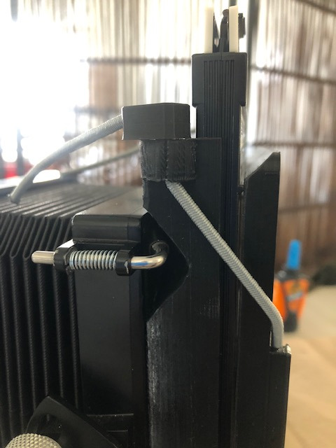
The shock cord run can be seen in this illustration. The ends are held by cord grips in this case, but knots could be used. The cord is intended to be run through the tunnel at the base, but in this prototype there is a length of 18 gauge wire with loops providing anchor points.
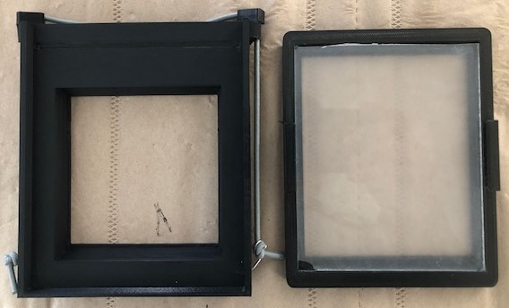
The ground glass frame was borrowed from a Will Travel camera. The frame has a channel on each side that takes the shock cord and allows the frame to adjust when slipping in a film holder, and to provide adequate tension for the light trap. The 90x90mm opening to match the Galvin rear standard can be seen through the ground glass. The exact framing and position of the focused image will depend a bit on the lens focal length (angle of view) and the type and amount of movements in use
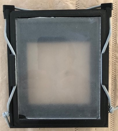
This particular ‘ground glass’ is actually acrylic sheet. The ground surface was produced using fine sandpaper in a large oscillating sander. This particular sander has a short, rapid oscillation and a sanding area almost as big as the sheet. This avoids regular marks and an uneven surface. With powered sanders it pays to use slightly coarser sanding material than if it was being done by hand. If the ‘glass’ is a plastic, like acrylic, avoid applying pressure, use clean sandpaper, and limit cycles to 10 seconds or so. Check the results frequently.
In Use
The standard Galvin back is removed to a safe place, and the adapter back is installed vertically with the holder inserting from the top. The ground glass will show the illuminated area, which is approximately 90x90mm. This will vary a bit depending on the lens focal length, and any movements applied.
Because the 4x5 holder is not centered over the Galvin back, using a roll-film holder intended for 4x5 cameras will not work very well.
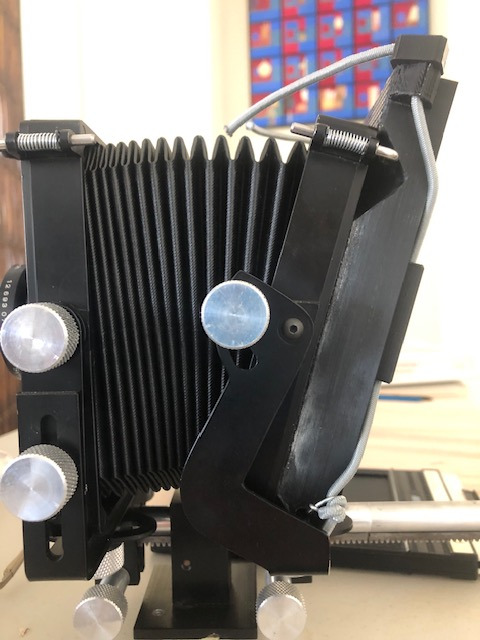
By keeping the new back as shallow as possible, a decent degree of rear tilt is possible. Currently this is plus or minus 15 degrees.
The theoretical standard lens would be 125mm ( 127 = sqrt( (90 x 90) x 2) ), so the lens choice is not really affected, especially if the 90x90 frame is cropped a bit at printing. Lenses designed with 4x5 in mind will have plenty of coverage. Lenses designed for 6x9 (3x2 in.) may be a bit tight.
Materials
This particular project was made using SUNLU PLA+ filament in black, on a QIDI X-Plus printer.
The Ground glass frame came from Morton Kolve’s 4x5 WillTravel camera set on Thingiverse.
The shock cord came from ‘Sgt. Knots’ via Amazon.
The cut acrylic sheet for the ‘glass’ came from Tap Plastics who have a local store. They do a mail service.
A plastic-safe flat or matte black paint is required to reduce reflections on internal surfaces. Vallejo acrylic model paint will work. Matte paint has a slight sheen/texture, but absorbs light well. Flat black is typically smooth. On an unsmoothed 3D printed surface there may not be much to choose between them.