3D Printing
QIDI X-Plus Notes and Hacks
The Filament Feed
The filament feed on this printer consists of a bar which does not rotate. The spool just slips on the bar as it rotates. This works fine with semi-rigid filament like PLA or PETG. Soft filament like TPU just stretches. Feeding TPU can be enough of a challenge without resistance from the feed roller.
In the original arrangement filament spools are slid onto the bar and positioned using two friction adjusted spool retainers. Most spools have a larger center hole than the rod, so the rod is offset from the center of the spool. As the filament is drawn from the spool, it tries to climb the rod, and then slips and readjusts. This provides some back tension, and keeps the filament tight on the spool.
The Filament Feed Hack
This is a quick solution to the resistance problem. It is not as satisfying as a proper bearing/rotating rod modification, but it has the benefit of being quick and in my case used some scrap I had on hand. I will probably do a bearing modification if I do a lot of TPU printing in future.
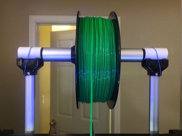
I cut two pieces of PVC pipe that had an outside diameter of about the same as the bar on the printer. The inside is smooth, and larger than the plastic ends on the bar. Each piece was cut to fit on top of the mount for the printer bar, and inside the end stop. The small elastic bands are not critical, but do help stop the pipe pieces disappearing into the machine when changing filament. The cut ends need to be smoothed.
In use the bar now rotates inside the pipe pieces with a little bit of friction. Since the pipe pieces are not fixed, the mounting can be reverted to the original mounting very quickly.

The printer is shown with the modification and with the TPU filament going direct to the extruder head. The normal filament feed is from the bottom through a short cable quide in the back of the printer and thence up to the top of the extruder.
Remote Print Monitoring
Because of the way our house is laid out, my 3D printer is a fair way from my office and computer. I have been thinking of adding a camera to the X-Plus for a while, and finally got around to doing it. I have an older Raspberry Pi B+ that has been freed up from a project, and a Raspicam camera module. I obtained a long (3 foot) camera ribbon so that the computer can be kept outside, and found a bracket and camera mount on Thingiverse that I could adapt for the limited internal space inside the printer. Although the X-Plus is a big unit, the internal space does not have a lot of clearance from the moving parts, especially when a sight line close to the build plane is required.
For most printers, using Octoprint is the easiest way to go, but the QIDI printers are not the simplest to interface with Octoprint. It is necessary, with the X-Plus, to use a serial to USB cable connected to the motherboard of the printer and a patch for Octoprint to allow it to handle the idiosyncratic firmware. I opted to use the approach described here.

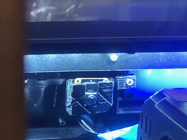
The camera is mounted close to the center line between the lcd and the backlit logo inside the upper front of the printer. The bracket uses an existing mount hole, and positions the camera at a slight downward angle while just clearing the print head. The ribbon cable is taped down along the front and comes out via the left side access panel. The right side panel cannot be used because the cable management for the printer sweeps that side.
A tweak to the focus may be needed - look up how to do it, as the camera usually has the focus glued in positoon for general use. The internal lighting of the printer is not great, but placing the camera close to the light source makes a reasonable compromise.
The computer sits outside the printer, so it is not affected by the heat inside, and runs in headless mode. I have it accessible via wifi and wired ethernet. The wired service provides a more stable feed, even if the viewing device is connected to the wifi side of the house network. I update the Pi by using SSH to connect to it and running manual updates.
Viewing is done using MJPG-Streamer, which provides the option of single image or streaming.

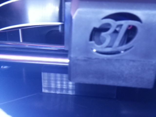
This static shot shows a print job under way. The part is currently around 1 inch (25mm) high, and is close to the centre of the build plate.
Raspberry Pi availability
The Pi was severely affected by the chip shortages during the COVID pandemic. Prices were artificially high, even if you could get one. Since I had an old one on hand that was not currently doing anything, and a version of the Pi Camera (actually the No InfraRed filter (NoIR) version), I had minimal costs involved - just obtaining a longer camera ribbon,
Running the MJPG-Streamer application does not require the Pi 4 or later. It should run on a Pi Zero with a command line interface. There are adapter boards to convert the Pi Zero to a Model B form factor, complete with 100Mbit ethernet
The new Raspberry Pi 5 is seriously faster than the Pi 4, but needs more power. It is way more computing power than is needed for just a camera.
Prototype prints
Is is certainly ideal for a design to be fully functional from the first print, but items with precise spacing, or a need to fit a real world part, sometimes need adjustments. Rather than print large objects, which takes time and materials, I often print just a slice through my work with the relevant bits to check. With OpenSCAD this is easily done by defining a suitable size ‘cube’ - sometimes just a narrow slice, sometimes a block almost the size of the buld volume - and doing an intersection operation with the portion of the design I want to test.
Ideally, this partial object should be printed in the same orientation as it will occupy in the full piece. That avoids any issues in the material bonding that might be hidden if it is printed in a custom orientation.
I find this is very useful for bolt and nut clearances, especially when they are not orthogonal to the printer axes, and portions that have to interlock with existing objects. Being able to print a cross section can help with fit adjustments.
Any test parts are separated by filament type and kept for paint testing or odd repair jobs.